.jpg)
.jpg)
The VF14 pentode valve was manufactured for a mere nine years and would be a long-forgotten museum-piece were it not for the fact that Neumann chose this unusual component as the active device in the impedance-converter for their now legendary U47 and U48 microphones. Unfortunately, the VF14 valve is now so rare that prices are astronomically high - and often for examples of dubious provenance and quality. This paper describes our journey to develop a modern equivalent of the VF14 in order to return these microphones to their original glory.

.... here at Hackaday we have a penchant for poking fun at the more silly end of the audiophile world.... It’s worth remembering though that this is not representative of the whole discipline of audio design, indeed the quest for perfect audio reproduction contains plenty of complex engineering problems. Phaedrus Audio ..... discuss the history of an unusual pentode tube used as an impedance converter in a series of legendary post-war microphones.....the story behind their design is one that should fascinate anyone. - Chasing A Long-Obsolete Tube by Jenny List. www.hackaday.com June 2020
After the Second World War, the collateral damage to German infrastructure was so severe that no nationwide electricity supply existed. Instead, many temporary and provisional mains electricity supplies were contrived; both AC and DC. As part of post-war reconstruction, there existed a market for cheap radio sets which could operate on all these various supplies – an unusual requirement because the sets running on DC supplies couldn't use transformers. To satisfy this demand, German valve manufacturers developed valves with a high heater voltage which could be run directly from the mains supply.
Since two-valve radio-sets were the most common and 110V AC and DC were the most common supplies (a contemporary design is shown below), the voltage chosen for the heaters was 55V, so that the two devices could be wired across the radio-set HT supply in series. The article declares, “Two valve universal voltage receiver with the new 55 volt valves ……. Simple, clear circuit; amazingly good reception and low power consumption.”
.png)
One such valve, widely used in radios of the period, was the VF14, a 55V heater version of the ubiquitous EF14 which was pretty much the volks-pentode of the German war machine, finding applications in everything from field radios to the Vergeltungswaffen Zwei (or V2) rocket!
The new German broadcast stations after the war had the same issue as civilians. Faced with a DC (110V) mains supply, Berliner Rundfunk (Radio Berlin) asked Georg Neumann to supply them microphones which could be used without a power supply: run directly from the mains. Neumann solved this in exactly the same way as the radio designers had, and opted to use the VF14.
But the requirements for the valve in the head amplifier in a broadcast microphone and in a cheap radio are very different. And, whilst the pedestrian VF14 valve worked consistently in the latter, only a few examples worked in the former.
Neumann's solution was to set up an arrangement with valve manufacturer Telefunken so that when they took delivery of a batch of VF14 valves, they selected suitable samples on the basis of: low grid-current; low-noise; low-distortion; and low microphony and the rejects were returned to the valve manufacturer. At least, two-thirds of the valves off the production-line were rejected for inadequate performance in the U47 and U48 microphones. Those that passed the Neumann test procedure were marked with an “M” on the side of the steel can (for Microphon).
In retrospect, Neumann's selection of the VF14 valve was an unfortunate choice for the active device in the impedance converter because only about twenty-seven thousand of these valves were ever made before production was halted 1954. The maths speaks for itself. We know that Neumann produced about 6000 U47s and about 800 U48 microphones. That’s about 7000 examples and, given the two to one rejection ratio, that means their valve consumption was about 21,000 of the 27,000 or so available VF14 valves.
This left only about 2000 suitable valves (6000 x ⅓) for the rest of all time. Not even enough units to allow for re-tubing the microphones once in their lifetime! In fact, even by the late nineteen-fifties, Neumann could not get hold of reliable quantities of the VF14 for production, maintenance and repair and the situation was so serious that, by 1960, Berliner Rundfunk refused further to invest in Neumann equipment unless the company demonstrated that it had a solution to keeping their substantial investment in U47s in service.
.jpg) Neumann’s rather hurried solution employed a 13CW4 Nuvistor (a miniature, metal-encapsulated valve, illustrated right) which fitted in a small board which could be plugged into the VF14 socket; a substitution which required a modification to the microphone itself and the associated microphone power-supply. This must have been very inconvenient for the broadcaster and must have caused Neumann some considerable embarrassment. Nevertheless, it is to the engineers' great credit that they didn't stoop to "revisiting" rejected VF14s and compromising the specification of their microphone.
Neumann’s rather hurried solution employed a 13CW4 Nuvistor (a miniature, metal-encapsulated valve, illustrated right) which fitted in a small board which could be plugged into the VF14 socket; a substitution which required a modification to the microphone itself and the associated microphone power-supply. This must have been very inconvenient for the broadcaster and must have caused Neumann some considerable embarrassment. Nevertheless, it is to the engineers' great credit that they didn't stoop to "revisiting" rejected VF14s and compromising the specification of their microphone.
By the end of the fifties, the Neumann design team knew that they had reached the end of the line. The U47/48 Nuvistor modification had never really found favour because it did change the sound of the U47 and U48 (for reasons which are explained later). And, it was clear by then that no more VF14 valves existed anywhere in the world with a specification suitable for their microphones. Moreover, extensive research at the time had revealed that no direct substitute valve existed.
Their response was to re-design the associated circuitry, and particularly the output transformer and release a new unit to replace the U47 and U48. This was the U67 microphone which employed the much more generally available EF86 valve. The U67 was launched in 1960 which was able to work as an omni’, a cardioid or as an eight.
Telefunken specified 5000 operational hours as the design-life of the VF14 valve, at which point gm was guaranteed as having reduced by only 30% and grid current to have increased only by a factor of ten. Of course, a valve can last much longer than this, but its performance will have deteriorated considerably.
It's over 600,000 hours since the end of the Second World War, and over 500,000 since production of the VF14 ceased in Berlin. These are massive spans of time in terms of the life of a vacuum-tube1 and, although the manner in which the VF14 is operated in the Neumann microphones tends to favour long life2, the inescapable fact is that any VF14M still operating today - even one boasting low-hours use - is well beyond its design life. The great expert on this was the late Oliver Archut, who wrote in a Neumann forum over fourteen years ago,
"Every VF14 used in U47/48 MM2/3 have outlived those manufacture given specifications. All VF14 tubes in 47/48 that I tested, barely meet the dynamic min. values to original Telefunken specs..... I know only ten original boxed [VF14s] world wide, but all the ones that I came across didn't or barely worked in microphones."
So, the situation is rather bleak for the owner of one of these renowned microphones because we can summarize the above as the following:
1 Note that Telefunken only specified the shelf-life of the VF14 for 30 years (and only 20 years for high-performance applications). So even NOS examples should be treated with a degree of suspicion and carefully tested before purchase.
2 The VF14M is operated with low electrode voltages which reduces the risks of leakage, and with a reduced heater temperature, which increases heater life. It is also operated at low power. However, convection cooling is poor and the VF14 runs quite hot. Remember, the U47 dissipates as much power as a Allstrom-Empfanger radio set!
In order to see why finding a substitute valve was so difficult – even for the Neumann engineers in the late nineteen-fifties when valves were in their “heyday” and lots of different types were still available – it is necessary to understand how Neumann used the valve in their U47/47 design.
.jpg)
.jpg)
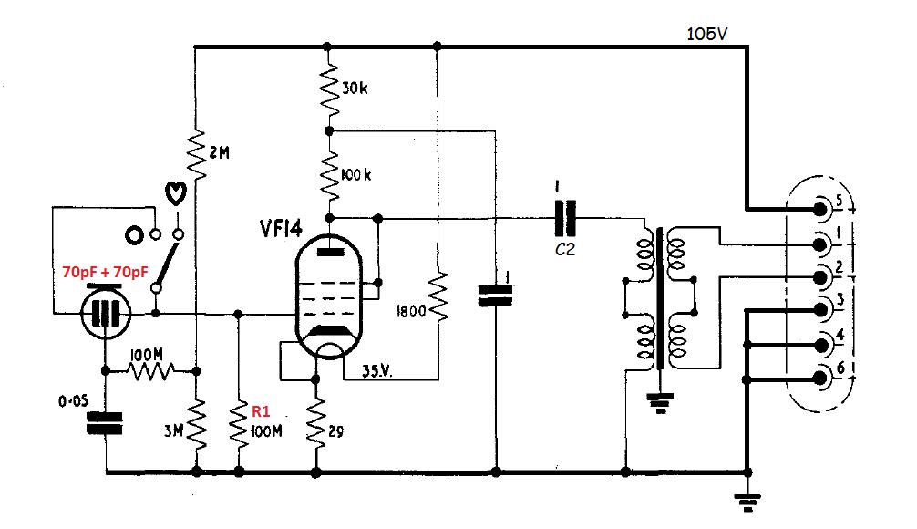
The U47 microphone is a switchable omnidirectional / cardioid microphone3. The microphone and its internals are illustrated left and right and the circuit diagram is given below. Note that the polar pattern is switchable by means of selecting the signal from one or both the diaphragms, either side of the common back plate - the latter forming the other, common, energized electrode. The back plate is held at a constant tension of about 55V and the charge is held steady by feeding this through a very large resistance.
3 The U48 microphone is almost identical to the U47, except for the selection of directional characteristics; the U48 offering the choice of cardioid and figure-of-eight instead of the U47's choice of cardioid and omnidirectional. Although this seems quite a radical change, in fact the circuit modification to bring this about is relatively simple.
The VF14M valve acts as a voltage amplifier circuit and drives the output transformer which drops most of the voltage gain of the valve, but translates the output impedance to drive the long microphone cable. As explained above, there is only one supply which is used for the HT and for the heater supply for the valve (under-run in this application at about 35V). The heater supply is simply dropped by the 1800Ω resistor which dissipates about 2.6 watts in the process.
The VF14 valve is strapped as a triode, with the additional, unusual feature that the suppressor grid is strapped to the anode, rather than the more usual cathode. More unusual still, the valve is operated with a very low anode voltage (circa 35V).
These conditions are well outside the normal operating and design envelope of the VF14 device and, in the majority of cases, this anode voltage is not enough to pull the valve out of grid-current. (This, along with low-noise and lack of microphony, was one of the principal conditions of the Neumann selection.) This also explains why the valves are operated at 63% of their specified heater voltage. By reducing the temperature of the cathode, the emitted electrons have a lower statistical kinetic-energy and the available space-charge of electrons is shrunk to that required to sustain the modest anode current. In this way, there are less electrons “all charged up with nowhere to go” which could contribute to a grid current4.
.png)
No manufacturer’s data exists for the valve in this under-run condition, so near to grid current, and with its electrodes connected in this way. And, in fifty years of scarcity, no-one seems to have published anything much to demystify the VF14’s performance in this role.
4 Technically the term is initial velocity current.
So, if we are to find a replacement for the VF14M, how should we decide on a comparable device? The only answer is to measure as many existing valves as possible, which is what Phædrus Audio has done over the past 5 years.
.jpg)
The equivalent output circuit of the impedance-converter of the U47 is given below. On the face of it, the diagnosis of the problem appears relatively straightforward the key parameters of the valve being anode resistance (ra) and mutual-conductance (gm). However, as with so many analogue circuits, the simplicity of the electronics disguises a dynamical system which is intricate and is greatly influenced by seemingly unimportant parameters. We shall see that it’s not enough that a U47 or U48 microphone “works” to prove that it has a suitable device fitted. Many valves will appear to work5, but they will not offer the performance of the original VF14M.
5Because of the fixed bias arrangement in which a back voltage is provided for the grid via the heater current flowing in the 29Ω resistor, the valve is relieved of the necessity to self-bias. This, and the low signal voltages involved, ensure that this circuit is not especially critical and almost any valve can be contrived to pass signal and work “after a fashion”. In a way, this is unfortunate because it encourages the belief that unsuitable valves (like old or rejected VF14s) are working properly.
.png)
Equally important is anode-resistance (ra). This parameter interacts with the primary inductance of the transformer to determine a low-frequency limit to the circuit. (Remember that the 100k anode-load is in parallel with ra in AC signal terms.) In a triode circuit, it will be the internal ra which dominates.
The anode resistance ( ra ) also acts as the damping in the resonant circuit formed by Cc (C2 in U47 circuit) and the primary inductance of the output transformer. This parameter has a disproportionate effect on the sound of the microphone being effectively part of an unmatched-termination, two-pole, high-pass filter6.
.jpg)
6 There’s a direct analogy here with a loudspeaker alignment and the performance of a particular drive unit in a sealed enclosure: an analogy which illustrates nicely that too low a value for ra will be equally as damaging to the correct response as too high a value: a little appreciated point. It’s also worth noting that the value of Cc (C2) changed during the lifetime of the microphone and as different transformers were employed; the earlier 0.5µF being replaced by a 1µF.
As a general rule, we can say that, if we want our U47 to sound anything like it did with a VF14M, the replacement device must match the gm and the anode resistance of the VF14 valve. And our substitute must offer similar linearity (or lack of it) and equal the grid-current performance of the selected VF14M. In addition, the inter-electrode capacitances of the device must match the VF14 because all these parameters influence the overall tone of the microphone. Finally, the value of rn, which is the equivalent noise resistance must be very close or the dynamic-range of the microphone will be modified.
Beyond these considerations, we must take into account the replacement’s physical structure, to ensure low microphony. And, ideally, we’d like our replacement to have similar heater requirements, so that the microphone circuitry itself shouldn’t have to be adapted. We also need to consider mechanical issues, the most straightforward being that the envelope be small enough to fit inside the case of the microphone.
The selection of the 13CW4 Nuvistor as a replacement for the VF14M by Neumann is interesting. The part possesses approximately correct ra and gm values (although the gm is on the low-side and variable operated away from its design centers). This, and a greater anode-grid capacitance, accounts for the lower sensitivity when the Nuvistor is fitted in the U47/48. It also requires a modification to the power-supply and to the microphone itself; because the Nuvistor requires more heater current. Nevertheless, it seemed a good starting point in our search for a VF14M replacement and our initial experiments were made with this Nuvistor valve which, happily, may still be obtained at reasonable cost.
Our experiments however confirmed the rather poor reputation for this substitution. The microphone gets hotter, the gain is low and the linearity is not especially good. Worse of all, the Nuvistor has a nasty habit of going noisy after a very short period. It is also microphonic. (These valves were designed as grounded-cathode RF amplifiers, so low-frequency noise and microphonics didn’t feature too heavily in the designer’s priorities!) The valve also has rather high electron-velocity current and this reduces the bass response of the microphone compared with the original, selected VF14Ms. (Sometimes this is attributed to a high anode impedance, but this is incorrect.)
Its lack of endorsement by recording engineers over the years is thus corroborated by real facts and we turned our back on this device as an approach to a VF14M substitute.
There emerged from our studies a couple of contenders as VF14M substitutes: the Western Electric WE407, a dual-triode; and the WE408a pentode.
The WE407a is a 9-pin, miniature small-button valve (see below) which may be made to fit neatly in place of VF14M. On the face of it, this valve does not seem suitable as a replacement for the VF14: the gm is too low and the ra too high. However, because the WE407a is a double-triode valve, there exists the possibility of running the two halves in parallel, which doubles the gm, and halves the anode-resistance. By this means, it has roughly the correct electrical parameters, and it has a heater which may be fed (slightly under-run) from the 105V supply. Better yet, it remains relatively cheap, so good examples may be selected on test from a larger batch (and they will need to be, as this valve was not designed for low-noise operation). But employing a strapped, double-triode implies double the anode-grid capacitance (which is already too high for a single valve), and double the grid current and these considerations tend to write off the WE407 as a suitable valve – at least, if we want to match what the microphone sounded like with a new, selected VF14M.
.jpg)
The existence of the WE408a was sufficiently encouraging that - undeterred by the datasheet for the WE408a which states, “… suitable for audio-frequency applications where exceptionally low microphonic noise is not a requirement”, we decided to make the WE408a the basis of a serious prototype choosing to mount these button valves inverted so that the extra height could be accommodated within the orientation spigot of the Y8A valve-base. Our prototype replacement is illustrated below.
.jpg)
Significant testing proved that either of these B7G valves can be made to work in the U47/48 circuit; although our preference was for the WE408a pentode. We believe that it is one or other of these two button valves which are found in the “plug and play”, VF14 “equivalents” from various manufacturers in which the small, glass-envelope BG7 valves have been contrived to reside in a housing made to resemble the original VF14(M)
However, these valves are not VF14s. Really the only points in their favour are:
Other than that, they are not really suitable. Points against include:
7 This is probably due to the much more advanced oxide cathode coatings of these much more recent valves.
These observations led us in a radically different direction...... a direction which led to the Phaedrus Audio VF14M Electronic TubeTM.
 Having experimented with all the known substitute valves for the VF14M, our ideas turned towards developing a circuit in which the characteristics of a brand-new VF14M were simulated rather than relying on the compromise of a vacuum tube “somewhat like” the VF14. The idea was to develop a “black-box” approach in which a circuit would behave exactly as the VF14M does in terms of its input and output impedance, transfer characteristic and transfer-function and use this to substitute for the original valve. Nowadays we are familiar with mathematical simulations of analogue circuits being employed to aid circuit-designers (as in the SPICE circuit analysis tools) and in software plug-ins for the musician. Why not apply the same methodology to emulate a valve?
The usual approach for the mathematical models for valves is to treat them as voltage-controlled current sources whose output current is a weighted sum of controlling element voltages raised to the power of 1.5. The equation for anode current (Ia) in a triode looks like this,
Ia = K × (µ.Vgk + Vak) 3/2
Where K is a parameter known as perveance, µ has the usual sense of an amplification factor and Vgk and Vak are correspondingly the voltages on the grid and anode with respect to the cathode. (Remember that the VF14M, despite being a pentode valve, is wired as a triode inside the U47/48 microphones.)
This is a powerful model for a valve which is operating with a high anode voltage and which is well away from grid-current. In other words, when a valve is operating well within its operational envelope. Unfortunately, those are not the conditions under which the VF14M is operating inside the Neumann microphones. Instead, the valves operate in a region where the exponent is not 1.5 and the effect of initial electron velocity (one of the components of grid current) is not insignificant in relation to anode-current. So, the eventual simulation is arranged so that the output signal current (Ia) is a function ( H ) of µ.Vgk (the AC signal voltage), Vak and a third term (Vi) such that,
Ia = H (µ.Vgk + Vak + Vi )n
where Vi is an equivalent voltage related to the initial electron velocity and n is a suitable exponent.
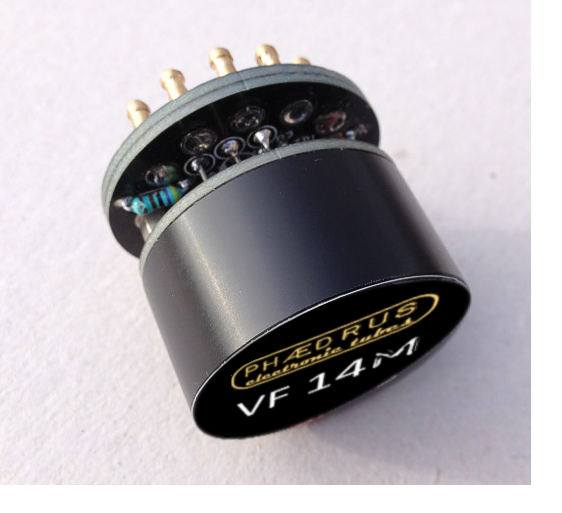
Devices obeying these principles we decided to call Phædrus Audio Electronic TubesTM.
_small.png)
With all these elements active in the overall simulation, we were able to “create” a valve which performed very closely to the original, selected VF14M. Not only were all the port voltages of the valve closely simulated, but even the dissipation of the device was set so that it is exactly that of a new VF14. And the size of the device was designed to closely resemble that of the original valve. The final design is illustrated above. The code name for this version was Phaedrus Audio VF14M Electronic TubeTM.
The curves below illustrate the frequency response* of the U47 with the Phædrus Audio VF14M Electronic TubeTM fitted (red curve). Note that the bass response does not fall away in relation to the original Neumann response (black curve - measured with an original VF14M valve).
Unfortunately, old VF14 valves and the various substitutes based on "button" valves both display this falling-bass effect (blue trace). This is because the grid-current is too high and these valves "suck charge" off the capsule - thereby reducing bass-response.
The grid-current of the Phædrus Audio VF14M Electronic TubeTM on the other hand, is carefully designed to match that of Neumann's selected VF14 valves (marked with the all-important M).
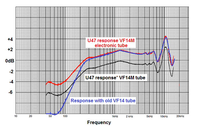
*Frequency response measured relative to a reference pressure microphone: sound source presented directly on axis with U47 in cardioid condition. The curves are offset by 2dB for clarity only.
Neumann's technical specification for the U47/48 was relatively threadbare regarding noise performance. Most technical specifications for the product omitted any figures for noise at all. One exception to this appears in a spec' given in a German cut-sheet for the product published in 1958 and shown below.
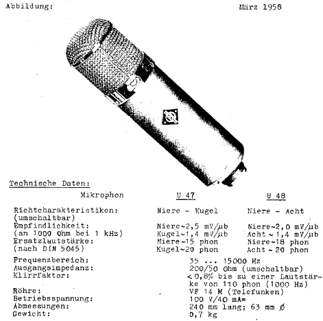
At least here we have some specification for Ersatzlautstarke or equivalent noise. Unfortunately, the specification is garbled, with self-noise being quoted as the higher (20 phon) value for Kugel (literally "ball" or omnidirectional), and the lower figure (15 phon) being quoted for Niere ("kidney" or cardioid). This is clearly wrong because the sensitivity of the microphone as an omnidirectional is quoted as 1.4mV/µBar which is exactly 5dB below 2.5mV/µBar which is the sensitivity for cardioid condition. (This would mean the dynamic range of the microphone differed by 10dB depending on the configuration which is clearly impossible! We shall see that consideration of the circuit leads to the same conclusion: the noise voltage in the omnidirectional condition will always be lower than when the microphone is in cardioid configuration.)
Once we have unravelled this ancient muddle, we have a solid data-point for noise of 20 phon for the open-circuit noise-voltage of U47 operating as a cardioid when measured with DIN 5045 standard weighting.
Firstly, let's get back to voltages from the curious "phons" specification. Neumann's 1µBar reference point for sensitivity is 10 times (20dB) below that of the point used today of 1 Pascal, an overpressure which is taken to be equivalent to an SPL of 94dBSPL.
Thus, the U47 (cardioid) sensitivity is quoted as 2.5mV (RMS) voltage in a sound field of 74dBSPL.
Taking "phons" here to be equivalent to dBSPL, we can therefore say that the noise-voltage is (74 - 20) or 54dB below the nominal sensitivity....... This is 5µV in RMS voltage terms.
Circuit considerations
Nearly all the noise in a capacitor microphone is generated in the high resistance grid (or gate) resistor necessary for the bias current of the head amplifier (R1 in the diagram above). Being entirely reactive, the capsule itself cannot generate any noise and the head amplifier shouldn't add too much if it's been designed properly and the tube is in good condition. The noise in R1 is reduced by the shunt capacitance of the capsule across it, as well as other strays and inter-electrode capacitances, the dominant component being the capsule itself.
The noise generator in the U47 is therefore 100MΩ with about 70pF in parallel in cardioid configuration. Or 100MΩ with 140pF shunted across it in omnidirectional configuration. (It should be obvious now how the noise figures for omnidirectional and cardioid are obviously transposed in the Neumann literature illustrated above. Clearly, the increased capacitance in omnidirectional configuration reduces the generated noise.)
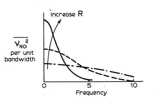
By the standards of its day, 100MΩ is a very large-value resistor (and this had replaced the 60MΩ component in the 1940s versions of the U47). However, by today's standards, this is a relatively low value; modern microphones employing values as high as a Gigohm in this position. The reason for the choice of very high values is that, as the resistance of R1 rises, the breakpoint at which the reactance of the capsule equals the resistance falls and the overall noise in the circuit appears to fall once it is weighted in a measuring network which rejects low frequencies. The weighting is the crucial point here: Although noise in a higher resistance circuit will actually always be more, because the noise weighting rolls-off low frequencies, the noise generated is "slid further down the weighting curve" and thereby apparently reduced. The curves below illustrate this effect.
Noise weighting
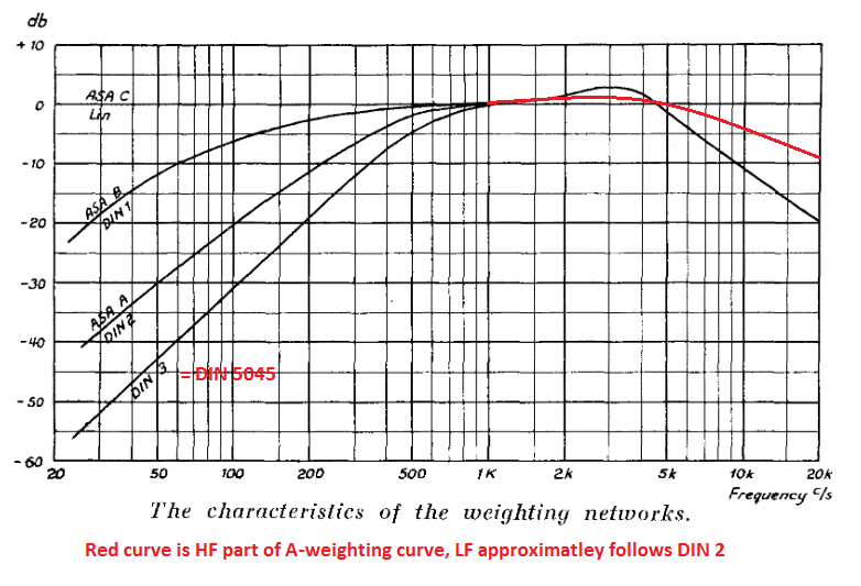
Nowadays A-weighting is the fashionable filter for measuring noise. But it was not always so. As the Neumann product data shown above reveals, Neumann preferred a weighting curve defined by the German standards organisation (DIN). Fortunately we still have accurate data for this NAB 5045 curve and it is possible to synthesise a circuit to replicate it. Phædrus Audio built a noise measurement filter to this specification to ensure that the Phædrus Audio VF14M Electronic TubeTM matched (or bettered) the original Neumann noise specification.
Results
With the Phædrus Audio VF14M Electronic TubeTM fitted in the U47 circuit (but with the capsule replaced by a 70pF capacitor), the total measured noise RMS voltage is 3μV when measured with a DIN 5045 weighting-circuit. We can therefore say that VF14M Electronic TubeTM matches the Neumann specification with a comfortable margin.
The most detailed specification of the U47/48 transfer characteristic is given in the German Neumann cut-sheet given above. Here they state that the complete microphone will offer less than 0.8% THD in a 1kHz sound field of 110 Phon. No absolute maximum sound-intensity is specified.
The Phædrus Audio VF14M Electronic TubeTM matches this transfer characteristic curvature, so that, at 110dBSPL, the harmonic distortion is approximately 0.6% at 1kHz. Distortion (as with a real valve) is almost entirely second-harmonic8. The actual figures for distortion at 110dBSPL at 1kHz for the Phædrus Audio VF14M Electronic TubeTM installed in the U47 circuit are: 2nd harmonic = 0.5%; 3rd harmonic = 0.3%, 4th harmonic = 0.05%.
8 This is actually a low level of harmonic distortion at an intensity some 16dB above nominal level (95dBSPL). Being predominantly second-harmonic, and therefore relatively inaudible, it is hard to attribute the magic "U47 sound" being due to harmonic-distortion as is so often claimed.
Of course, the ultimate test of any audio component is, "What does it sound like?"
We provide some of our perceptions below (as well as some advice about how comparitive tests should be organised). But, ultimately what counts is your impressions. Contact sales@phaedrus-audio.com to audition a Phædrus Audio VF14M Electronic TubeTM.
HF response
The U47 is such a big microphone that the effect of the body upon the incoming sound is profound. Whilst the on-axis response of the U47 is relatively flat (see graph above), the frequency response from directly above the microphone (end-on response) has notches and peaks of as much as 20dB in the 6kHz to 10kHz region, and the overall sensitivity in this direction is only a few dB below the on-axis response.
In our experience, when recording a U47 signal in a reverberant field (like a standard studio) it is possible easily to be fooled that there are changes in this frequency region due to a slightly differing microphone position. (Remember that the half-wavelength of 6kHz in air is less than 3cm.) The time taken to dismantle the set-up, install the alternative tube, re-rig the microphone and re-seat the musicians makes mistakes like these very likely unless extreme care is taken with the geometry of the tests9. Comments concerning differences in HF sound-quality should therefore be treated with suspicion unless extensive precautions have been taken to ensure consistency between trials.
More convenient comparisons may be achieved by bypassing the microphone capsule and feeding an audio signal direct to the grid of the valve via a capacitance equal to that of the capsule. Tests of this type demonstrate that there are substantially no response variations with the Phædrus Audio VF14M Electronic TubeTM in the HF region of the microphone's frequency response.
9 The frequent habit of rigging the U47 upside-down means the end-on response is picking up the floor reflection and this exagerrates this effect.
Low frequencies
The LF response is another matter. The Phædrus Audio VF14M Electronic TubeTM is the only substitute for the VF14M which we have measured which replicates the response below about 500Hz and this is easily heard. This change not only changes the way the microphone sounds, but it changes how it may be used. It enables the microphone to be used further from the talent (as it was designed to be) because it is not necessary to use the proximity-effect to make up for a falling bass-response.
The differences don't end there of course. The Phædrus Audio VF14M Electronic TubeTM will not age like a tube. There is no heater to fail and no cathode to be poisoned or deplete. The VF14M Electronic TubeTM thereby offers a reliable financial investment and guarantees many more years of consistent service from these wonderful microphones.

Address all mail to sales@phaedrus-audio.com