
The transistor was invented at the tail-end of the 1940s and started to replace valves (vacuum tubes) throughout the following decade. But there remained some rôles in which valves reigned supreme for a further 10 years. Ironically, due to a better understanding of electron ballistics, the last decade of development of this old technology resulted in some remarkable devices which still find a place in modern audio.
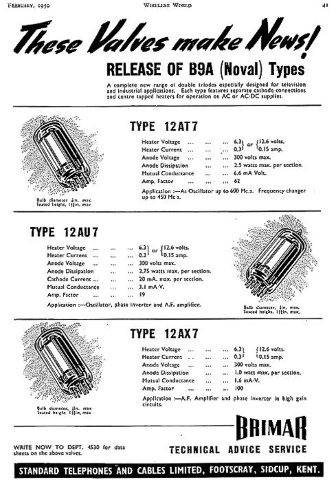
One of the most common families of valves found in audio equipment is the nine-pin (B9A) single-envelope, double-triode, in which two triode valves are integrated within the same glass envelope. Introduced around 1950, these devices are: used as balanced circuits in professional equipment; shared across channels in stereo hi-fi equipment; employed as phase-splitters in audio power amplifiers; and “cascaded” to form two-stage amplifiers. These tubes are the "staples" of audio design, in everything from guitar stacks to phono preamp's.
All these tubes have datasheet transconductance (or mutual conductance gm) values from around 1.5mA/V (12AX7) to around 6mA/V (12AT7) where transconductance is defined as.
gm = (δIa⁄δVgk)Va = k
or, in words, the degree to which the anode current changes for a volt change on the grid electrode.
We shall see that the values quoted on datasheets are optimistic later. But why should we care about this rather recondite parameter?
Because the lower limit of electronic noise in a valve circuit is defined by the device transconductance, . (Actually this is equally true of bipolar junction transistors and FETS.) High gm is important if we want to create low-noise preamplifiers.
The random, thermally generated noise in any resistance R is given by this equation,
Vn = √ [ 4 k T B R] RMS volts ............... (equation A)
where k is Boltzmann’s gas constant (1.38 x 10⁻²³ joules/ degree Kelvin), where T is absolute temperature in degrees Kelvin (K = °C + 273), B is bandwidth in Hz of the measuring set-up.
The equivalent (voltage) noise in the input circuit of a tube operated as a triode is given by the equation,
= √[ 4 k T B (2.5/gm) ] RMS volts
Simply put (compare with equation A), this equation represents the electrical noise generated by a resistance 2.5/gm in the grid circuit.1
Noise isn't really generated in the grid circuit. It's just convenient to consider it this way. The noise in a triode is generated in the randomness in the rate at which electrons arrive at the anode, or in the random fluctuations in the anode current. The greater the effect of the changing grid voltage upon the anode current, the less these random fluctuations count in the overall anode signal. This is the reason why transconductance is inversely proportional to the equivalent noise of the tube referred to the grid.
With dual, small signal triodes, with practical transconductance limited to a few mA/V, the equivalent noise-resistance is limited to about 1kΩ, a value very much higher than the source resistance of (for example) a moving-coil phono cartridge or a ribbon microphone.
The extraordinary mutual conductance of the space-age tubes of the 1960s is principally due to incredible precision manufacturing-techniques because, to quote Spangenberg,
❝ ..... the mutual conductance of a triode depends primarily upon the cathode-grid spacing. The smaller the cathode-grid spacing, the larger the mutual conductance.❞³
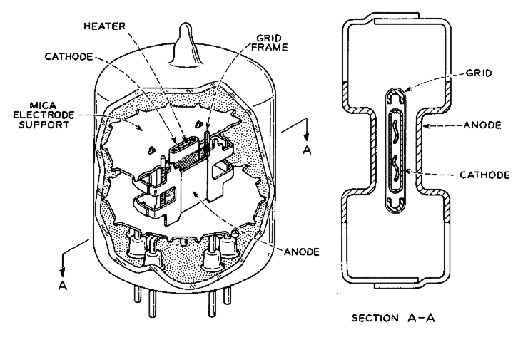
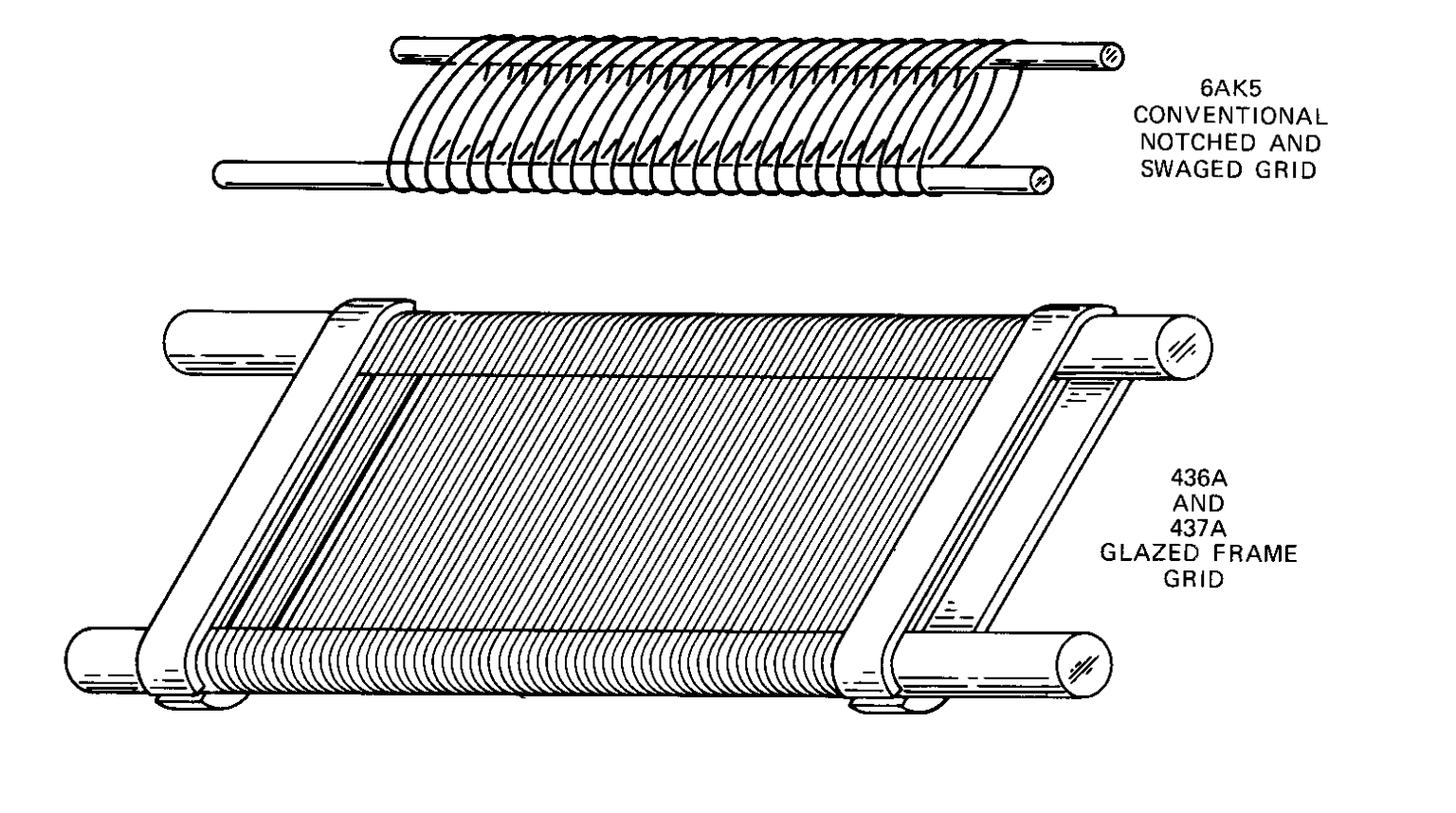 The 0.0035-inch (89µm) cathode-grid spacing of the wartime 6AKS tube is about the minimum for conventional construction techniques (shown right).
Studies showed that to improve gm, the cathode-grid spacing would need to be reduced to 0.0025-inch (64µm) and this required that the grid assembly be greatly more rigid. The solution was the frame grid; one of the last innovations in vacuum tube design.
In the 437A tube for example, the grid is made by winding tungsten wire with a diameter of 0.0003"or 7µm, (one-tenth the diameter of human hair) onto a molybdenum frame and then brazing the wire to the frame with a small amount of gold. To prevent the mechanical modulation, the grid wires are wound (at around 400 turns per inch) in such high tension that the working stress of the grid wires supasses that of architectural steel.² The great tension on the grid wires was arranged to minimise microphonics.
The construction of these high gm tubes was truly the swansong of the thermionic era. They are a combination of particle physics and watchmaking! (The way the geometry of a tube relates to the electrical parameters is covered in Appendix 1.)
The mutual conductance (gm) of any valve is proportional to a one third power-law of anode current. Double the anode current and you increase gm by 26% (because 2⅓ = 1.26). This is the reason why headline transconductance values given by the manufacturer are a bit misleading because they assume operation at the highest anode current which may be inconvenient for other reasons.
But there's no getting away from it: low noise is secured by operating the input stage at a higher standing-current than you would normally expect.
The last vacuum tubes were developed in the 1960s for television and multiplexed telephony signals in the 400 -500MHz range. Low-noise (and low-impedances) were required for these duties and - because transistors were not yet able to deliver much power at these frequencies - the tube manufacturers' R&D departments developed a series of devices with exceptional transconductance figures.
Example high gm tubes of this period include:
| Device | Headline gm | 2.5 ⁄ gm | Base | Dissipation |
|---|---|---|---|---|
| EC8020 | 60mA/V | 40Ω | B9A | 8 watts |
| WE437A | 43mA/V | 60Ω | Magnoval | 7 watts |
| WE417A | 25mA/V | 100Ω | B9A | 4.5 watts |
| EC8010 | 28mA/V | 90Ω | B9A | 4.2 watts |
| 6C45П | 45mA/V | 56Ω | B9A | 7.8 watts |
| D3a (triode) | 41mA/V | 60Ω | B9A | 4.5 watts |
| E810F (triode) | 45mA/V | 56Ω | B9A | 5 watts |
These high transconductance vacuum tubes may be sought out - even today. But these tubes were never mass market devices sold to the public: the precision manufacturing techniques prevented that. For example, when it was developed, the D3a pentode was the most expensive tube Siemens ever produced.
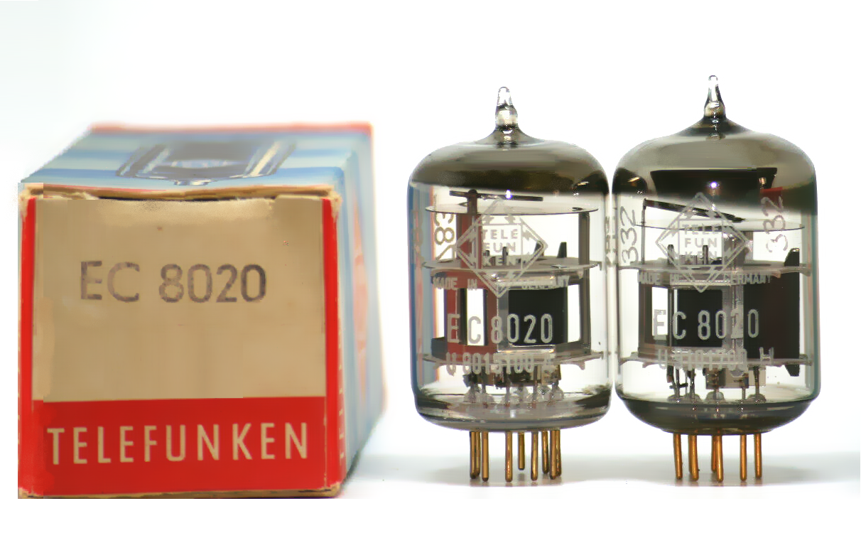
The record for gm is still held by the EC8020 manufactured by Telefunken in the 1960s with an amazing transconductance of 60mA/V. It was developed for UHF repeaters for PAL television signals. It too was never sold to the general public. Today it is almost impossible to find. In fact, remaining stocks of all the tubes listed in the table are limited and are depleting fast.
And that's a real shame because, without access to these tubes, we are limited to valves which have an equivalent input noise of around 500nV in a 20kHz bandwidth. On the limit for use as (for example) as a phono preamplifier.
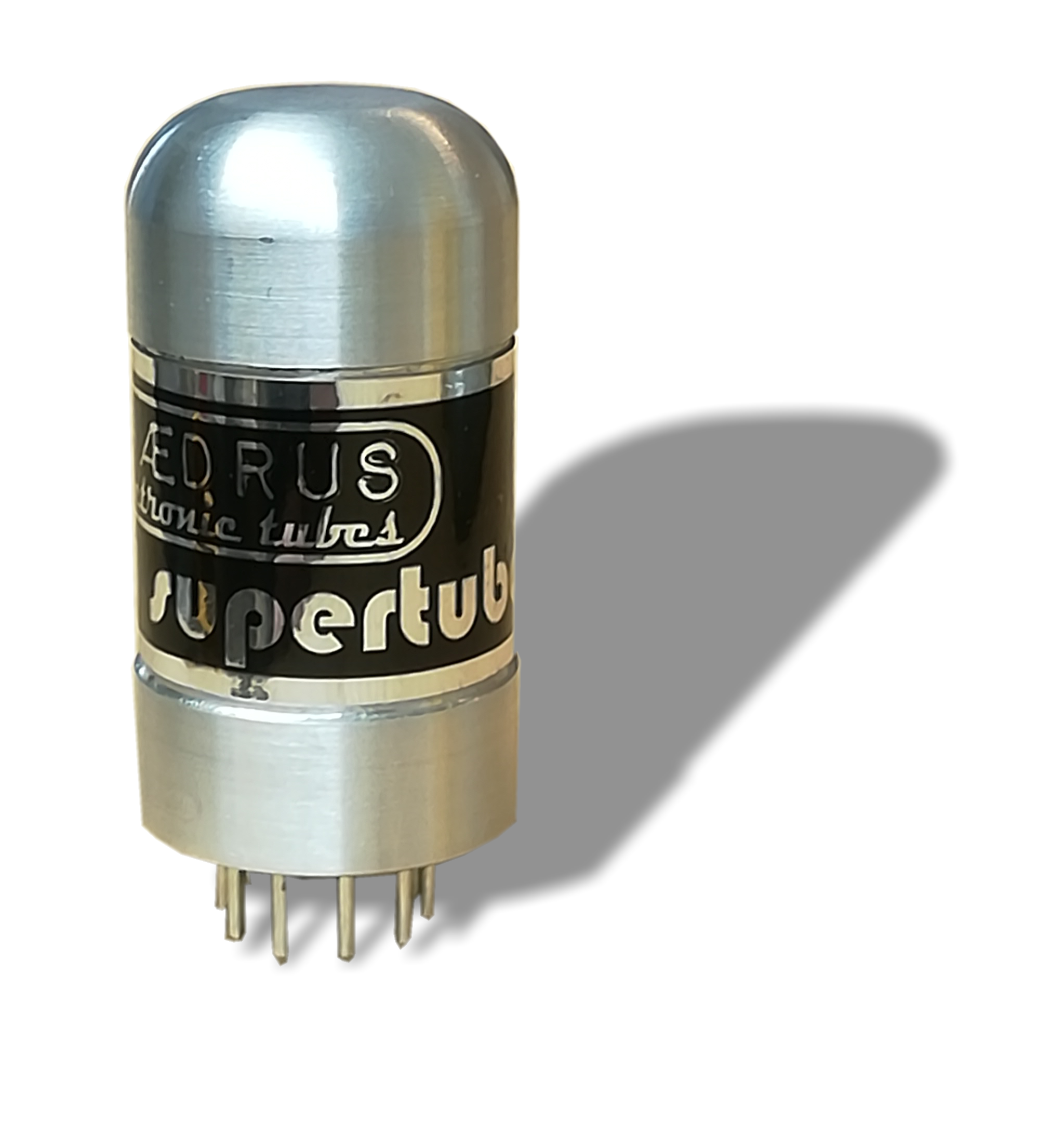
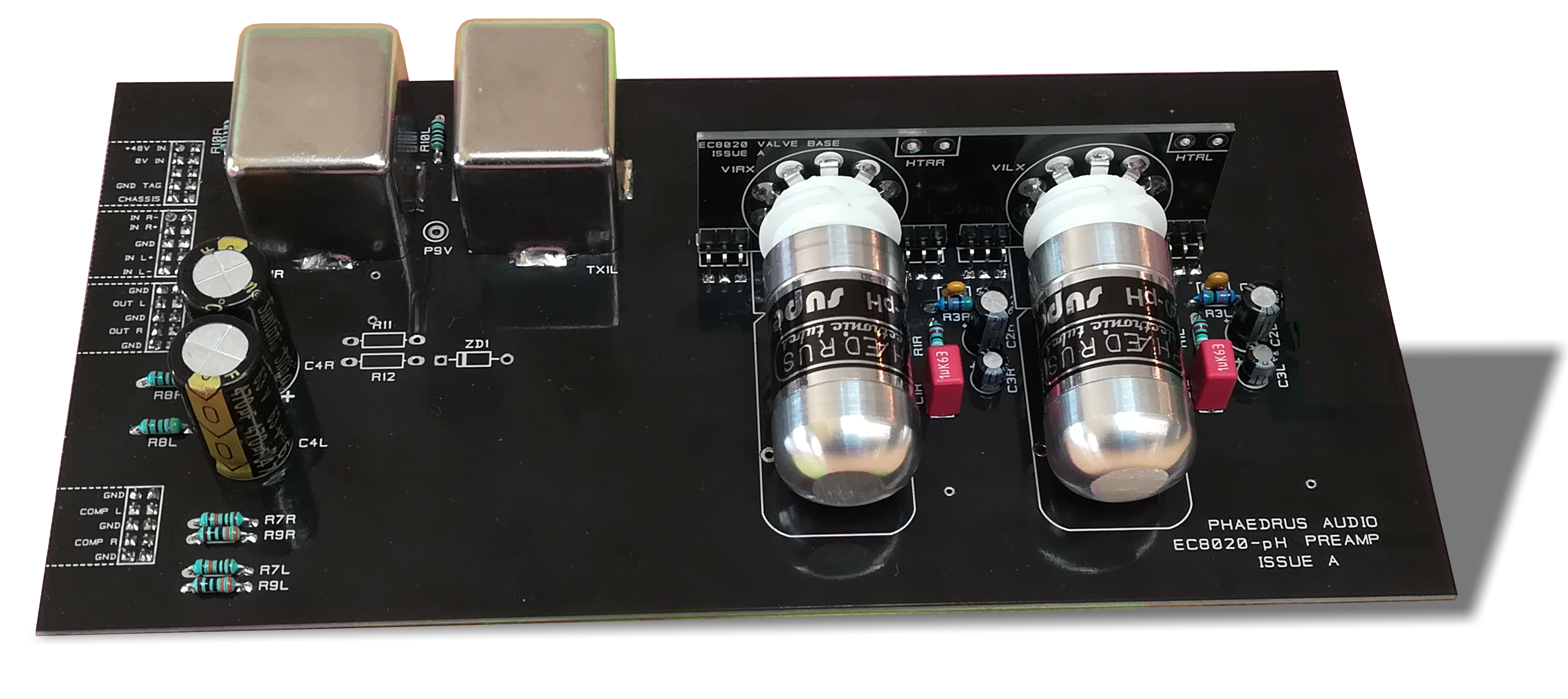
The Phædrus Audio EC8020-pH electronic Supertube™ is designed to fulfil the role of very low-noise preamplifier tube and may be regarded as a substitute for any of the tubes given in the table; although the pinout and transconductance value follow the EC8020.
To aid the circuit designer, the EC8020-pH achieves its headline transconductance at a much lower quiescent current compared with the original Telefunken device. Low noise operation may thereby be achieved with reduced anode dissipation.
 This is important because the original tubes could all support bulb temperatures above 150°C and upwards of 5 watts of anode dissipation; raising the anode temperature to 500° to 600°C. The Phædrus Audio EC8020-pH Supertube™ is limited to 1 watt anode dissipation.
Using the Phædrus Audio EC8020-pH, it is possible to create low-noise preamplifier of exceptional quality with a single device (see below). The simplicity of the circuitry is enhanced by a greatly reduced heater requirement. The Phædrus Audio EC8020-pH tubes are well matched and they do not suffer from the tendency to self-oscillation at very high frequencies — an effect which beleaguers all the original high gm tubes. Grid-stopper resistors (which degrade noise-performance) are not required.
Click for a preliminary datasheet for the Phædrus Audio EC8020-pH.
Address all enquiries to sales@phaedrus-audio.com
An electron tube (valve in British English) is, of course, an electronic device, but its performance depends on the mechanical arrangements and geometry of the electrodes. This link between the mechanical and the electronic is, no doubt, one of the ongoing fascinations with valve technology.
But how precisely do the various tube parameters we know as circuit designers' relate to the disposition of the electrodes inside the envelope?
Before we start, let us revisit how the triode valve works (only the triode is considered here). Here we will quote M.G. Scroggie (of Foundations of Wireless fame) who seemed to have a way of describing electronics with an almost biblical simplicity.4
❝.....De Forest tried adding a third electrode as a sort of tap to control the flow of current between cathode and anode. It is called the grid, and usually takes the form of an open spiral of thin wire wound closely around the cathode so that in order to reach the anode the electrons from the cathode have to pass between the turns of wire.If the potential of the grid is made positive with respect to the cathode it will assist the anode to neutralize the space charge of electrons around the cathode, so increasing the anode current; and, being nearer to the cathode, one grid volt is more effective than one anode volt. If, on the other hand, it is made negative it will assist the space charge in repelling electrons back towards the cathode.❞
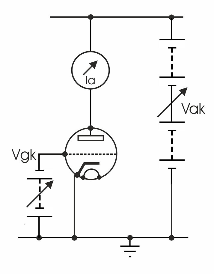 Let us take the simple circuit (right) and use it to establish two important parameters of a valve. And let's imagine that we have a rather special valve in which we can move the grid and the anode relative to the fixed cathode. We can perform two distinct experiments.
Firstly, we arrange a small, constant, negative voltage on the grid terminal with respect to the cathode (Vgk) and vary the much greater, positive voltage on the anode, Vak to see how the change in voltage at the anode affects the change in the flow of current (Ia) from anode to cathode using the ammeter in the anode circuit. Mathematically we can express our findings like this,
(δVak ⁄ δIa)Vgk = constant
This derives the important parameter for a valve known as ra or dynamic anode resistance in terms of volts/amp or ohms.
We notice that we can affect the value of ra significantly by moving the anode relative to the grid and cathode. The further the distance the anode from the grid, the less the effect of the electric field of the anode upon the cathode and the less the change in current Ia for a given change in anode voltage Vak.
We say, the further the anode is from the cathode and grid, the higher the measured value of ra.
We also notice that altering the distance of the grid from the cathode (which is, in any case, a much smaller distance than the distance of the anode from the cathode) has very little effect upon ra.
Now we perform a second experiment in which we hold Vak constant and vary Vgk, to see how that affects the change in anode current. We can write our finding like this,
(δIa ⁄ δVgk)Vak = constant
This experiment reveals the transconductance or mutual conductance of the valve, expressed as gm in amps/volt (or, more often milliamps per volt, mA/V).
We experiment with the anode position and notice that it makes very little difference to the anode current - and thereby to the transconductance of the valve. However, moving the grid relative to the cathode - even by a tiny amount - has a great effect in the change of anode current for a given change in grid voltage.
To summarise our experiments, we have discovered that:
Now we modify our rather special experimental valve so that we close-up the spiral of wire which forms the grid so that the turns of wire are closer together. We do this without changing its distance to the cathode or to the anode. Now we repeat the same two experiments we performed before.
We notice, somewhat unexpectedly, that the change in the form of the grid has a small effect on gm but has a significant effect or ra. It seems that, the denser the spiral of wire of the grid, the more it casts an electrostatic "shadow" on the cathode. We say the grid screens the anode and the less effect a change in anode voltage has on the anode current - or the higher the value (in ohms) of ra.
To summarise again:
For completeness, if our experimental valve allowed us to increase the surface area of the cathode, this too would increase gm because transconductance is directly proportional to cathode area.
Armed with the two parameters of ra, and gm, we can calculate a most important parameter for a valve known as μ or amplification factor because
μ = gm × ra
μ is important because it appears in the anode current equation for triodes which brings together the effect upon Ia of both Vak and Vgk and where the μ term operates to represent the amplified effect of the grid voltage upon anode current compared with the anode voltage.
Ia = K × (µ.Vgk + Vak)n
K is a constant (the perveance) which is particular to any one type of valve and n is a constant, often taken to be 3⁄2.
It might occur to you that, since the amplification of a triode is related to the ratio of the electrostatic influence of the anode to the electrostatic influence of the grid, measurement of the two capacitances: 1) from grid to cathode and 2) from anode to cathode would reveal μ directly.
In fact it does! The ratio of these two capacitances produces a value known as μe or the electrostatic amplification factor which experience reveals is very close to μ as derived above. But, before you rush off to confirm this from valve datasheets, the capacitances are tiny and the extra capacitances due to lead-frame, connection pins etc. obscure the capacitances due purely to the electrode configuration.5
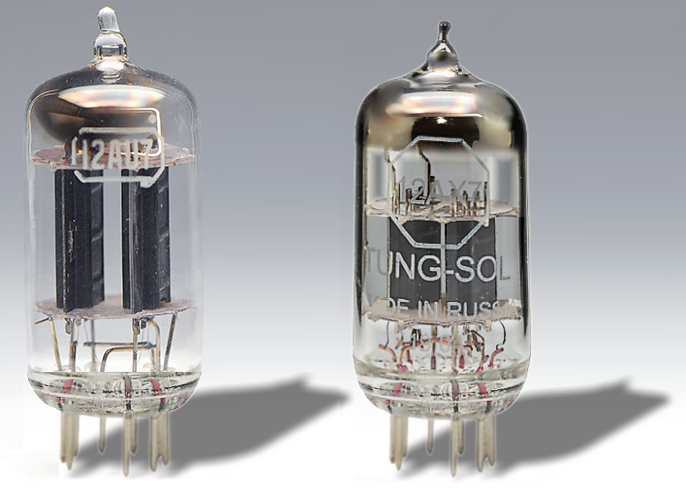
We can use this knowledge of how electrode geometry affects μ, gm and ra to compare valves of different types. Of course, we can't tell everything from a cursory visual examination of the valve. The anode usually obscures an examination of the grid construction and spacing. However, we can make a few educated guesses.
The 12AX7 (right-hand valve) is compared with the 12AU7 in the adjacent photograph. The 12AU7 (left) has a thin, long anode, close to the long cathode at its centre. We can therefore expect a low anode resistance because the electric field of the anode will have a strong effect on the flow of electrons. We therefore expect a low μ device. This is indeed the characteristic of this valve.
It's brother, the 12AX7 has a fatter, shorter anode, further from the cathode at its centre. So, we can expect a higher ra and a higher μ. We might expect too a lower gm because the area of the cathode is reduced compared with the 12AU7. These are indeed the characteristics of this valve type.
1. The Radiotron Designer's Handbook, F. Langford-Smith, Wireless Press, Sydney, Fourth edition, 1952
2. A History of Engineering and Science in the Bell System Electronics Technology (1925-1975) Prepared by Members of the Technical Staff, AT&T Bell Laboratories. 1985 AT&T Bell Laboratories.
3. Vacuum Tubes. Karl R. Spangenberg Mcgraw-Hill Book Company, Inc. New York 1948
4. Foundations of Wireless & Electronics. Scroggie, M.G. Eighth edition Butterworth & Co (Publishers) Ltd London 1971. Marcus Scroggie, came from forebears strong in faith and evangelical fervour and - apart from his well-known contributions to electronics - was closely identified with the Baptist church all his life.
5. Principles of Electron Tubes. J. W. Gewartowski and H. A. Watson (Members of the Technical Staff Bell Telephone Laboratories) D. Van Nostrand Company, Inc. Princeton, New Jersey 1965.

Address all mail to sales@phaedrus-audio.com