
Read Sound on Sound magazine's review of the PHAMULUS.

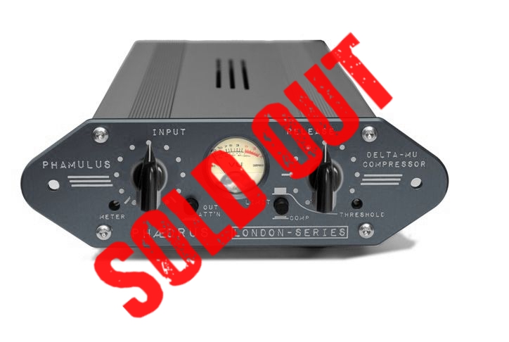
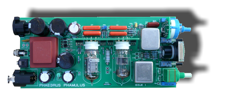
The Altec Lansing 436C δμ compressor amplifier (above) dates from the nineteen-sixties. The circuit of the Phædrus Audio PHAMULUS II is based upon this circuit. The PHAMULUS II is an improved version of the original PHAMULUS in new grey livery and with an improved compression metering circuit.
A famous, but rare variant of the Altec Lansing 436 is the Abbey Road studio RS124 which included a modification to the Altec input circuit to include a matched-impedance attenuator. Importantly, from an artistic point of view, the original Altec circuit only included a variable release time preset, so this was added as a user-control by the Abbey Road engineers too. This greatly increased the scope of the compressor's duties to which has been attributed some of The Beatles' magic. The entire unit was retro-fitted with a house-designed escutcheon which disguised its Altec heritage.
The variable release user control has also been adopted in the design of the Phædrus Audio PHAMULUS such that the control allows for adjustable release times between 0.1 sec (much faster than the original Altec) and 1.3 sec. This faster response widens the applications of the Phædrus Audio PHAMULUS to include compression duties for - amongst other things - drums.
 |
I recently added the Phamulus II (Vari-Mu) compressor to our hybrid/outboard studio, mostly to track RnB/Jazz vocals. After a few sessions I can say that this little unit (its size is diminuitive compared to the usual 19" rack designs) absolutely blows vari-mu's many ŁŁŁ more expensive out of the water ! Whatever the team at Phaedrus have done with the original Altec Lansing circuit - the result is a unit which excels at and showcases what vari-mu compression is all about - smooth / controlled / creamy / airy and never laboured even at high ratios. Perfect job guys and at Ł600 an absolute steal. Peter M (Producer / Summer Hill Music).

Type: Compressor Amplifier
Gain: +30dB (reduced to +20dB with output attenuator engaged)
Frequency Response: ±1.5 dB, 40Hz to 15kHz
Max Output Level: >+20 dBu (as straight amplifier at 1kHz)
Harmonic Distortion: At 25 db of compression: Less than 1.5%
Noise Level: 74 dB below rated output (—111 dBm equivalent input noise)
Input Impedance: 15k bridging transformer (earth-free)
Load Impedance: Normally bridging: 600 ohms if ordered specially
Maximum Compression: 30 dB
Attack Time: 50 milliseconds
Release Time: 0.1 to 1.1 seconds
Threshold: Adjustable: 0 dBm to -16 dbm output
Compression Ratio: 2:1 at 0 dBm threshold; 4:1 at +16 dBm threshold
Controls: Gain, Threshold, Release Time, Output atten', meter-trim,
Power Supply: 12V AC, 4 Watts
Tubes: 6BC8, 12AU7
Address all mail to sales@phaedrus-audio.com